Location: Home >> Detail
J Acoust. 2020;2:e200002. https://doi.org/10.20900/joa20200002
 ,
Sridhar Santhanam
,
Sridhar Santhanam
Department of Mechanical Engineering, Villanova University, 800 Lancaster Ave, Villanova, PA 19085, USA
* Correspondence: Shahrooz Mark Jahanbin, Tel.: +1-979-422-4479.
This article belongs to the Virtual Special Issue "Ultrasound Nondestructive Evaluation"
Damage nucleation and growth can be complex in hybrid bonded structures composed of metals and laminated composites. There are limited reliable analytical and empirical methods to evaluate the bond integrity of such structures and to quantify the state of bonding in hybrid joints. Depending on the geometry and accessibility to hybrid joint sections, ultrasonic Nondestructive Testing (NDT) techniques are available for inspection of these structures. The interfacial damages at the bondline of structural joints represent challenging detection tasks for traditional ultrasonic nondestructive inspection (NDI) methods such as the pulse–echo method. This work investigates a method for bonded joint inspection that uses interface guided ultrasonic waves propagating along the bondline of these hybrid joints. An analysis, based on the use of finite element models for hybrid structures, is conducted to examine the use of interface waves to detect common defects found at or in the vicinity of interfaces of hybrid isotropic-anisotropic structures. Both cohesive and adhesive damage in a bonded joint are examined. Several damage scenarios are numerically studied and the guided wave time of flight (TOF) is shown to be sensitive to the size and location of interfacial damages. The results of this study suggest that interface guided waves can be used for integrity assessment and damage detection in hybrid structures.
The use of hybrid structures with customized mechanical properties and adaptive functional performance is gradually changing traditional design concepts. Hybrid structures are composed of two or more sections, typically with different materials, which form a joint that is either co-bonded or co-cured in the manufacturing process. A typical hybrid structure in aerospace applications has one section of metal with the other being a composite laminate or honeycomb face-sheet. Presently these configurations are used in the design concept of aircraft parts like wing structures to benefit from the superior load bearing capabilities of metallic parts and the fatigue resistance and weight-saving features of composites. Other instances of hybrid bonded structures include repaired sections where a composite patch is used to repair a metallic structure or vice versa. There are also complex repair configurations where composites with lower cure temperature are used as scarf or patch. Some hybrid joints are composed of ceramic and laminated or honeycomb composite sections. In some applications to avoid corrosion between metals and CFRP, layers of different materials might be used at the interfaces, and for composite—composite hybrid interfaces, a layer of adhesive might be used.
Damage nucleation and growth behavior in hybrid structures is a complex phenomenon which can govern residual strength and fatigue life. To mitigate widespread fatigue damage, the integrity of structures needs to be monitored to avoid unexpected failure. Different Nondestructive Testing (NDT) methods can be employed to examine the structures without permanently altering the material and its properties. The objective of this study is to develop a method for interfacial damage detection at the interface of hybrid bonded joints.
The failure mechanisms in hybrid structures, or collectively for adhesive bonded joints, are not properly standardized. Two failure types can be identified at these joints: adhesive failure and cohesive failure. Cohesive failure is attributed to failures within the adhesive material or within one of the other materials directly adjacent to the bondline. The term adhesive failure is ascribed to failures at the boundary between materials, such as the boundary between the adhesive and one of the adherends. There is also a newly developed concept called adherent failure which is the far-field interlaminar fracture, specific to composite structures. Regardless, the bonded load path is a chain of materials and interfaces that form the adhesive bonded joint. The strength of the bond is determined by the weakest link in this chain. If the damage is due to failure of materials, coatings and adhesive, then the bonding process is probably reliable, but if the failure is due to an anomaly in any of the interfaces between substrates and coatings or between the coatings and the adhesive the bonding process is not reliable.
Generally failure at a boundary of the adhesive and adherend is troubling because that might be a sign of inappropriate process. In the aerospace industry, adhesive failure is considered fundamentally unacceptable by regulatory agencies such as FAA. Hence damage modeling of the bonded joint is focused on the damage nucleation at surface–coating-adhesive interfaces and on the degradation of the adhesive layer itself. Figure 1 shows the adhesive failure and cohesive failure regions in the bonded joint.
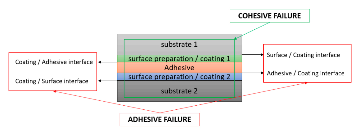 Figure 1. Adhesive and cohesive failure regions in bonded joints.
Nondestructive testing with ultrasonic guided waves has emerged as a very effective approach to locate and identify defects in structures. Guided waves such as Lamb waves propagate along the length of thin-walled plates [1–4]. Guided waves are also known to propagate along the surface of structures as well as the interface of two bonded materials. The wave propagating along the interface between two solids is called a Stoneley wave [5]. Interface Stoneley waves exist for certain combinations of materials [6–9]. Interface waves possess good characteristics such as large displacement and high energy at the interfaces of two materials. Since the defects of interest in our study of hybrid joints are located at or near interfaces, interface waves offer a mechanism by which such defects can be detected and localized.
There have been a limited number of studies performed in the analysis of interface waves at the bondline of isotropic and anisotropic media. Scala and Doyle published a theoretical [10] and experimental [11] study of waves in orthotropic–isotropic interfaces. Other studies have used mathematical approaches for various applications [12–17] involving interface waves. With recent developments in powerful numerical tools, the interface wave propagation for a range of materials can be explored. The propagation of interface waves in anisotropic media, specifically layered hybrid structures, has been studied in recent research on interface waves. Finite element analysis is used by researchers to simulate interface wave behavior at isotropic—anisotropic hybrid and composite interfaces [15]. McCarthy & Georgiou [18] first explored the use of finite element analysis for surface wave propagation problems. Gardner and Rose used the finite element method (FEM) to assess the feasibility of inspecting interfaces between composite and metallic layers using ultrasonic interface waves [14]. Frehner and Schmalholz used FEM to simulate Stoneley guided-wave reflection and scattering at the tips of fluid-filled fractures [19]. Maghlaoui et al. presented a numerical simulation of the transient ultrasonic wave reflection at a liquid-solid interface [20]. Other researchers (McMillan [21], Bossi et al. [22] and Nagy et al. [23]) have employed the same numerical technique to study the interface guided wave behavior for different applications.
The primary focus of our study is to develop a damage detection approach for hybrid bonded joints of a metal and an anisotropic composite layer using interface waves. Our approach and method of modeling interface guided waves at the bondline of hybrid bonded joints is described in Section “NUMERICAL FINITE ELEMENT SIMULATIONS”. In Section “DAMAGE DETECTION WITH INTERFACE WAVES”, the results of several finite element simulations are presented for the numerical modeling of interface wave interaction with cohesive and adhesive damage. In general the approach involves the use of a pristine hybrid bonded joint and its interaction with an interface wave as the baseline problem. Then several cohesive and adhesive interface defects are introduced in the structures with different sizes and locations with respect to the bondline, and their interaction with interface waves are simulated. Changes in wave propagation parameters such as displacement magnitude and time of flight are utilized to identify the presence of defects. Our conclusions are presented in Section “CONCLUSIONS AND FUTURE WORK”.
Finite element simulations are conducted to study the existence and propagation of interface waves, as well as their interaction with defects, in hybrid, layered metal/composite structures. The Dynamic Explicit solver of ABAQUS is used for the simulation of wave propagation. This solver solves the dynamic equations of motion. Discretization of the domain into nodes and elements leads to the standard linear global equation:
MÜn + Kun = Rn
Here M is the mass matrix and K is the stiffness matrix. un and Rn are the global vector nodal displacements and nodal forces at discrete time instant n. The central time difference integration scheme is used to solve for the nodal displacement vector with the time step chosen to ensure a stable and convergent solution.
Interface waves propagate along the bondline between two distinct, connected regions. Only certain material combinations provide an environment for these types of waves to propagate along the interface [8]. The existence and behavior of interface waves depend on the mechanical properties of the interfacing sections at the bondline. If the mechanical properties of interfacing sections at the bondline are not too different, then the interface waves do not form (Figure 2a). Otherwise the interface waves form at the bondline of dissimilar materials with large differences in mechanical properties (Figure 2b).
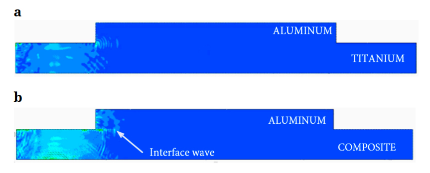 Figure 2. (a) Interface wave does not exist at the bondline of an Aluminum-Titanium hybrid joint. (b) Interface wave does exist at the bondline of an Aluminum–Laminated Composite hybrid joint.
The upper section in Figures 2a,b is aluminum. The lower section is titanium in Figure 2a and a laminated carbon reinforced composite in Figure 2b. An interface wave does not form at the bondline between aluminum and titanium of Figure 2a due to the similar mechanical properties of the two materials. The arrow in Figure 2b points at the formation of interface waves at the bondline of the upper aluminum and the lower composite sections. The velocity of a bulk wave is higher in aluminum than the composite as a result of the fairly substantial difference in mechanical properties of the two materials, which creates favorable conditions for formation of a propagating interface wave. For modeling interface waves in hybrid structures, a few important criteria and steps need to be considered for simulation. A forcing source or actuator should be placed near the interface (see Figure 3), in order to initiate the travelling waves that will be guided by the interface. Parameters such as frequency of the actuation, mesh size, the length scale of the model, and time domain should be carefully chosen.
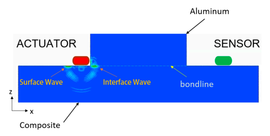 Figure 3. Configuration for modeling interface guided waves in hybrid structures.
For this study the upper section of the model is metallic (aluminum). The lower section is a laminated CFRP composite with the ply orientation in different directions. The ply orientation of the laminated composite layer at the interface with the metallic section is critical for determination of interface wave existence. Each lamina in the composite laminate is a single ply with typical ply thickness of 0.2 mm. Typical fiber orientations in the laminate are 0°, −45°, +45° and 90°.
The sections of the hybrid structure are represented in Figure 4. The plane-strain 2D model is constructed from an isotropic section on top with dimensions 101.6 mm × 38.1 mm, bonded to the anisotropic composite section with dimensions 254 mm × 38.1 mm at the bottom. The isotropic section of this joint is aluminum with elastic constants, E = 68.26 GPa, and Poisson’s ratio, ν = 0.3. The composite section is a laminated carbon fiber reinforced polymer with each ply of the unidirectional layer possessing four elastic constants, E1 = 137.9 GPa, E2 = 10.34 GPa, G12 = 6.89 GPa, and ν12 = 0.34. The anisotropic section is built up by composite layup tools in ABAQUS to form a balanced, symmetric laminate with stacking sequence (0,+45,−45,90,−45,+45,0)s and all the unidirectional plies are meshed accordingly. Table 1 lists the materials used in construction of the hybrid bonded joint structure. The finite element simulations utilize plane strain (PS4) continuum shell elements. The element size was chosen based on the frequency of excitation and the expected wavelength of the propagating wave. The sizes of the elements were always chosen to be one-sixth or less of the wavelength of the propagating wave.
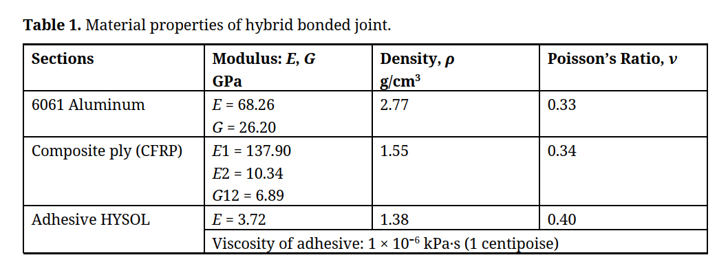 Table 1. Material properties of hybrid bonded joint.
The model is constrained for translation and rotation at the two upper corners of the metallic section and the two lower corners of the composite section (Figure 4). An excitation source or actuator (a node) is placed on the composite section at one end, and a receiving sensor is placed at the other end of the bondline. A Hanning-windowed, five-cycle burst of a sinusoidal signal was used as the pulse excitation signal. The initial forcing frequency was set at 1 MHz to model the interface wave. Additional frequencies ranging up to 10 MHz excitation have also been used to investigate the influence of frequency on wave propagation and damage identification.
In order to avoid interference between the interface wave and waves generated by boundary reflections from the edges of the domain, the outer material boundaries were placed far enough away from the forcing source and the interface, to eliminate the effect of reflection. This was ensured by selecting the thickness of both material sections to be sufficiently large compared to the wavelength of the wave.
An important parameter in studying interface wave behavior is the velocity of wave propagation. The changes in velocity of interface waves can be used to find critical information about interfacial and sub-surface states of hybrid structures at the bondline. It is well known that the Rayleigh wave velocity of each of the bonded media in a hybrid joint is lower than the Stoneley wave velocity propagating along the bondline. Moreover the Stoneley wave velocity is lower than the shear wave velocity in the denser of the two media of the hybrid structure [7]. For the material and joint configurations in this numerical study the Stoneley wave velocity in unblemished hybrid structures is determined using finite element analysis.
Figure 4 shows the details of the finite element model utilized for interface wave velocity determination. Two points (nodes) on the bondline and in the pathway of a propagating interface wave packet are shown as points 1 and 2. The distance between the points is 50.8 mm and the wave speed can be calculated by the known Time of Flight (TOF) between the two points. The TOF of the wave between point 1 and point 2 are determined from the displacement-time plots of the finite element model.
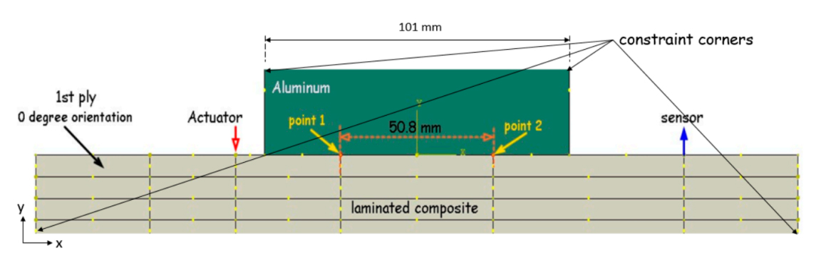 Figure 4. Geometrical description of hybrid bonded joint.
In hybrid structures, the wave propagation behavior is different on the two sides of the bondline due to different mechanical properties and wave velocity components. In the vicinity of damage, usually a wave mode conversion occurs with the scattering source at the center of damage. The scattering effect results in a changed wave energy distribution that eventually causes disruption in the propagation characteristics of traveling waves as shown in Figure 5. The disruption in the pathway of traveling wave is different for each damage type, size and location.
Crack-like damage or disbonds are defined in ABAQUS/CAE by introducing a seam crack in the mesh. A seam defines an edge in the model that starts off being closed; under the application of loads during an analysis, the seam can open just like a crack does in a structure. This is facilitated by the placement of overlapping duplicate nodes along the seam.
Figure 5a represents the interface wave front propagation along the bondline with no damage. Disruption caused by a disbond at the bondline of the hybrid joint is evident in Figure 5b, where a bow wave forms at the free edge of a disbond crack. In Figure 5c, the presence of a delamination below the bondline causes a Lamb wave to form between the delamination and the bondline.
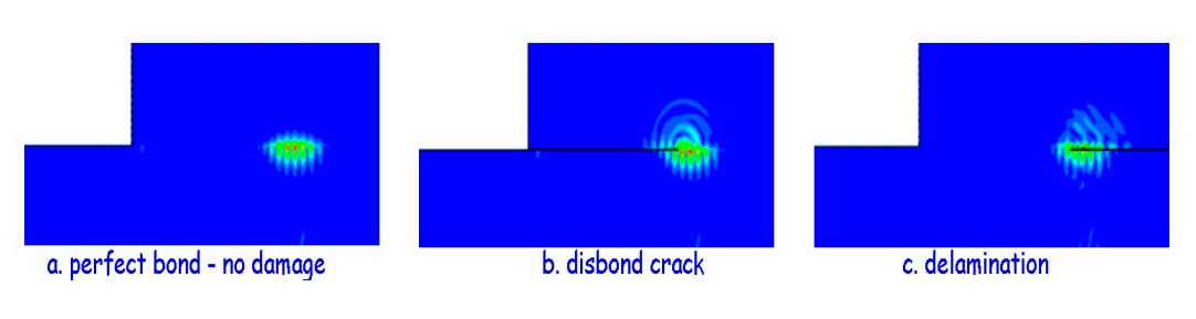 Figure 5. Interface wave forms in hybrid composite–metallic joints in the absence and presence of damage at or near the interface.
Generally surface and interface waves are non-dispersive, particularly if the elastic half-space consists of a homogeneous material, hence the phase velocity does not depend on frequency or wavelength. However in the hybrid metallic–composite structure configuration, the modes corresponding to guided waves in an elastic multi-layered half-space are usually dispersive. The dispersion curves of these guided waves are used to infer the structure properties of the multi-layered medium for Non-destructive Inspection (NDI) purposes. There have been other approaches for damage detection of bonded joints similar to hybrid structures by the use of other indicators such as signal difference coefficient, peak frequency shift, and wave structure [18]. Other research has also explored different techniques [24–26] to quantify the state and health of a hybrid bonded joint, but a reliable solution for the problem of bond strength prediction is still unavailable. In this work the explicit time domain and time of flight (TOF) analysis is used for damage detection.
Cohesive FailureInterface guided wave simulations are used in this work to detect cohesive bonding defects in hybrid structure joints. The velocity of the interface wave provides information about the damage e.g., size and location, by base-lining the wave behavior with respect to the undamaged and pristine condition of the structure. Disbonds, delaminations, matrix cracks, and fiber fractures are among the critical failure modes of hybrid structures; these are categorized as cohesive failures in hybrid joints.
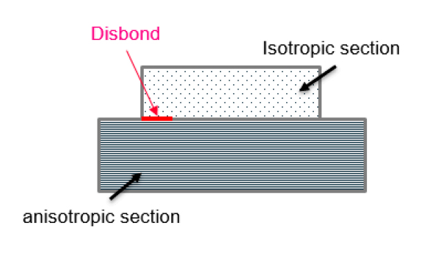 Figure 6. Cohesive damage—disbond.
For cohesive damage simulation, a disbond crack at one free edge of the bonded section (see Figure 6) is introduced and then the disruption in the interface wave propagation is exploited to calculate the delay in time of flight (travel time of interface wave from actuator to receiver). Several different disbond crack sizes (lengths) are considered ranging from 2.54 mm to 25.4 mm in an interface whose length is 101 mm. The mechanical properties for the isotropic section and the anisotropic section of the hybrid joint of Figure 6 are as shown in Table 1. Simulations are also performed for a pristine undamaged (UD) structure to provide the baseline. The travel time of the propagating wave from the actuator to the receiver is recorded. Wave motion in the x coordinate direction is perceived at a slightly different time than wave motion in the y-direction and hence these two travel times are differentiated.
Figure 7 shows numerical results for time of flight of interface waves. These time of flight results are computed using the displacement or motion in the direction of the interface (x-direction) as well as the direction normal to the interface (y-direction). Two different scenarios were considered for the lay-up of the composite section; one scenario considered a 0 degree orientation for the interface ply and the second scenario considered a 90 degree orientation for the interface ply. A range of disbond crack lengths were considered. Figure 7 reports results for an excitation frequency of 1 MHz.
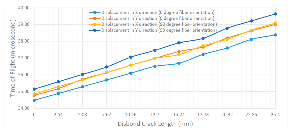 Figure 7. Time of flight for interface wave signal vs the disbond crack size (1 MHz).
As the size of damage increases the time of flight of the wave pulse increases. The time of flight recorded for the undamaged model is close to 35 microseconds. The time of flight for the largest disbond crack size (25.4 mm) which is about a quarter of the length of the bondline is close to 39 microseconds. The linear trend in time of flight indicates the interface wave speed decreases with increase in crack size. This is due to the mode conversion of Stoneley wave to Rayleigh waves along the exposed surfaces of the disbond crack. The velocity of Rayleigh waves is lower than that of the Stoneley waves for this material combination [24].
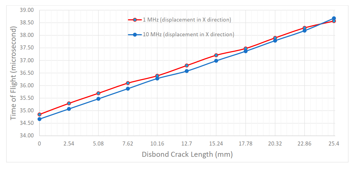 Figure 8. Time of flight for interface wave signal vs the disbond crack length (1 MHz and 10 MHz).
The interface wave is faster when the direction of wave propagation aligns with the fiber direction of the interface ply of the composite section (i.e., 0 degree ply at the interface is parallel to the wave propagation direction) when compared with the case where a 90 degree ply is the interface ply. A similar linear trend in time of flight results is seen for higher excitation frequencies; the results for both 1 MHz and 10 MHz excitation frequencies are shown in Figure 8.
Another form of cohesive damage is sub-interface cracks beneath the bondline, in the ply matrix or ply interfaces of the composite section of the hybrid joint of Figure 9. Ply matrix cracks are cracks that form in the interior composite plies. Delaminations are cracks that form at the interface of two plies in a composite laminate. Delaminations can be caused by contaminations, lack of compaction during the production and cure phase, or by the impact of an overheating of the cured material. In the bonded joints, where the adhesion strength of bond is high, ply matrix cracks and delaminations are located in close proximity to the bondline (see Figure 9).
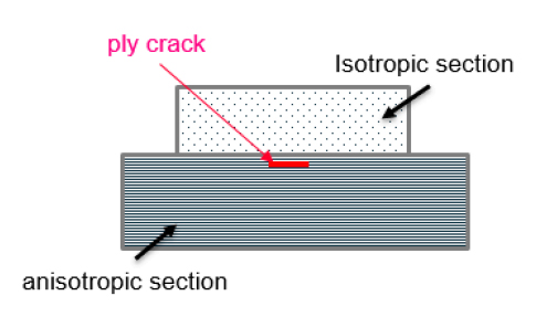 Figure 9. A delamination/ply matrix crack located close to the bondline of a hybrid metal-composite joint.
In this study, we examined the behavior of the traveling interface wave along the bondline, when the size and location of the ply matrix crack or delamination damage is varied. The changes in the wave amplitude and delay in the time of flight of the interface wave along the bondline, are compared with the case of an undamaged and perfectly bonded baseline scenario.
Twenty five different damage scenarios are considered. These scenarios are generated by varying two parameters: the ply matrix crack length (or delamination crack length) and the offset location relative to the bondline. The crack lengths considered included 2.54 mm, 5.08 mm, 7.62 mm, 10.16 mm, and 12.7 mm. Each of these cracks is located at five different locations defined by the offset relative to the bondline. The offset distances are: 0.09525 mm, 0.1905 mm, 0.28575 mm, 0.381 mm, and 0.47625 mm. Offset distances of 0.1905 mm and 0.381 mm correspond to delamination cracks, while the other three offset distances correspond to cracks in the interior of plies and hence should be classified as ply matrix cracks. Figure 10 illustrates a scenario where the ply matrix crack is located at an offset distance of 0.28575 mm from the bondline in the carbon-fiber reinforced plastic section of the hybrid joint. The interface wave time-of-flight is determined for each of these scenarios as well as for the case of an undamaged or pristine bondline.
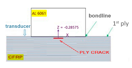 Figure 10. A crack located at an offset distance of 0.28575 mm from the bondline.
The thickness of plies in this model is 0.1905 mm. The interface wave frequency used for this simulation is 5 MHz. The wavelength of propagating interface wave in this case is 0.58 mm. The changes in time of flight with respect to the undamaged case (i.e., bondline with no defect) are shown in Figures 11–13. These are for the cases where the crack location offset distances in composite laminate are 0.09525 mm (Figure 11), 0.1905 mm (Figure 12), and 0.28575 mm (Figure 13), respectively. The vertical axis is the change in time of flight, which is the difference in TOF with damage and TOF without damage in microseconds. The horizontal axis is the length of the ply crack.
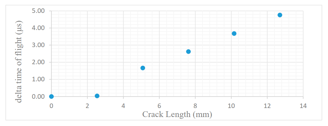 Figure 11. Delta (TOF) vs crack length for the offset distance of 0.09525 mm.
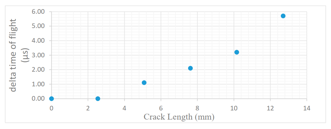 Figure 12. Delta (TOF) vs crack length for the offset distance of 0.1905 mm.
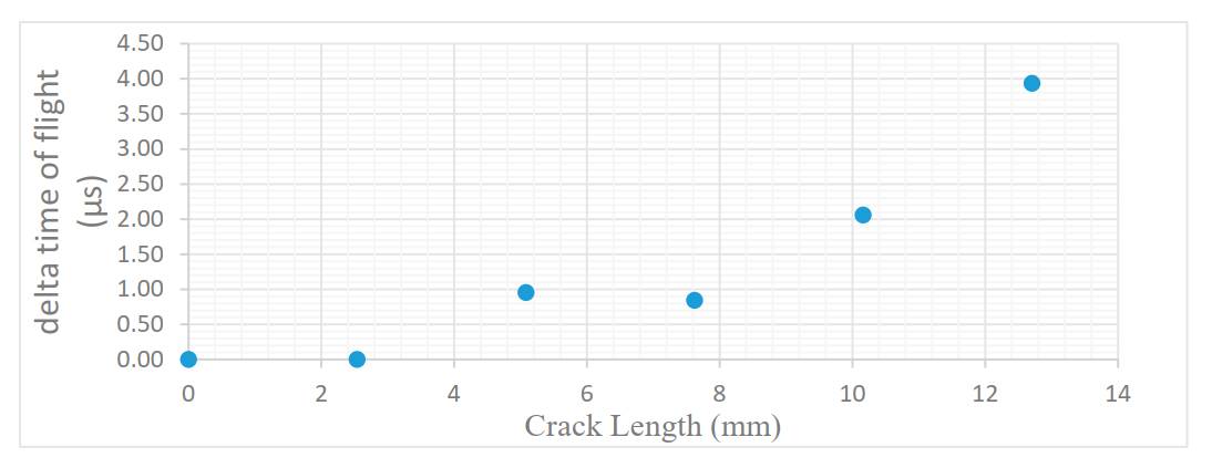 Figure 13. Delta (TOF) vs crack length for the offset distance of 0.28575 mm.
The time of flight is sensitive to size and location of the crack. When the crack length increases, the change in time of flight, (TOFdamaged − TOFundamaged), increases at fixed distance from bondline. The rate at which time of flight increases with crack length is not linear and depends on offset distance of the crack from the bondline. When the offset distances were set at 0.381 mm and 0.47 mm, the effect of the crack on time of flight of the interface wave was imperceptible. Hence, at these offset distances, cracks are invisible to the interface waves. The interface wave energy decays exponentially through the thickness of each of the two sections of the bonded joint and in particular in the composite section. Hence, the influence of a ply matrix crack on interface wave propagation can only be felt if the damage is close to the bonded joint interface. The maximum depth at which a crack can be located for it to be visible to the interface wave will depend on the wavelength of the interface wave. In the case where the crack is embedded deep in the composite section and far away from the interface, there are other ultrasonic methods like through transmission, which can be used to locate the depth of the defect by comparing the back-wall peak reflections with crack peak reflections. Methods such as through transmission and pulse echo are not effective for detecting the near interface cracks we have studied in this work.
Adhesive FailureIn this section we examine the existence of an adhesive layer (Figure 14) between the two bonded sections and the effect of the change in properties of the adhesive material, caused by adhesive failure, on interface wave propagation. The goal is to utilize the results to determine if adhesive failures can be detected using interface waves. Interface wave propagation is simulated in the interfaces between laminated Carbon Fiber Reinforced Polymer (CFRP) and aluminum alloy 6061 with HYSOL EA 9394 adhesive in between. Pristine properties for these materials have been tabulated in Table 1. For adhesive failure, the response of the interface waves to the changes in the properties of the adhesive material at the interface of an adhesively bonded joint are investigated. In Section “Cohesive Failure” it was shown that the velocity of interface waves decreases as the size of disbond cracks and ply matrix cracks and delaminations at or near the bondline increase. In this study the focus is on interface degradation in the form of changes in density of the adhesive layer present at the interface of a bonded joint. These density changes of the interface adhesive also interfere with the interface wave propagation.
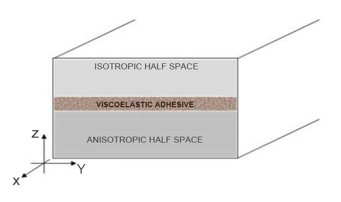 Figure 14. Hybrid bonded joint with adhesive layer.
Figure 15a,b illustrates the phenomenon that we hope to exploit in order to characterize the state of the adhesive at the bondline in a hybrid joint. Figure 15a shows the wave form attenuation in the vicinity of an adhesive layer with pristine density and modulus properties shown in Table 1, and Figure 15b shows the attenuation of the same wave form when it encounters an adhesive with reduced density. It is apparent that the adhesive properties have an effect on interface wave propagation.
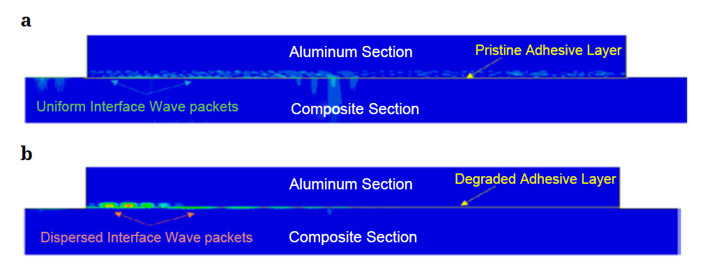 Figure 15. (a). Pristine adhesive—normal interface wave behavior. (b). Degraded adhesive with reduced density—abnormal, attenuated wave behavior.
The results of numerical simulations for interface wave propagation in the presence of adhesive degradation are presented here. A layer of viscoelastic adhesive with thickness of 0.254 mm is placed between the isotropic and anisotropic sections (see Figure 14). Adhesive degradation is modeled in this work by reducing the density of the adhesive. The basis for this assumption is that environmental effects such as excessive moisture do cause changes in the density of adhesives. Moisture absorption, for instance, can cause formation of voids in the adhesive, resulting in lower density.
Table 2 shows the interface wave time-of-flight (TOF) change with decrease in density of the adhesive layer. The results of Table 2 are also depicted pictorially as a bar graph in Figure 16.
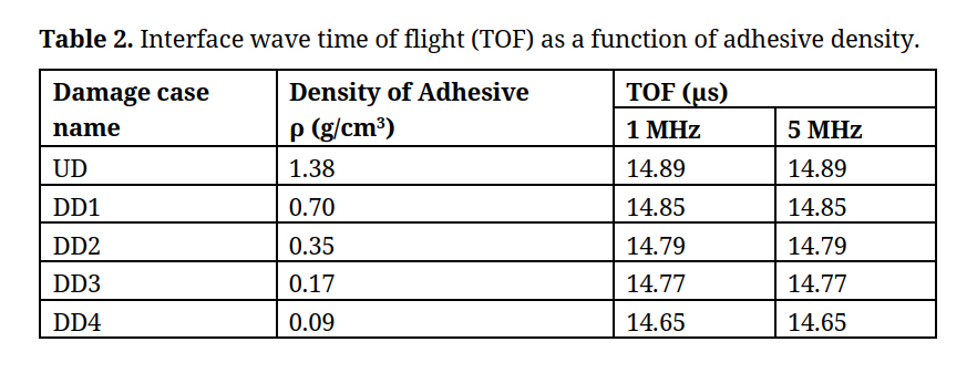 Table 2. Interface wave time of flight (TOF) as a function of adhesive density.
The results for excitation frequencies, 1 and 5 MHz, are identical and are as shown in Table 2 and in Figure 16. It appears that unlike cohesive damage, the changes in time of flight are independent of propagation frequency for adhesive damage. Also, the time of flight changes are in good agreement with the general equation for wave velocity in solid media, V∝√(E⁄ρ), in which the reduction in density is a contributing factor to increase in velocity of propagating wave.
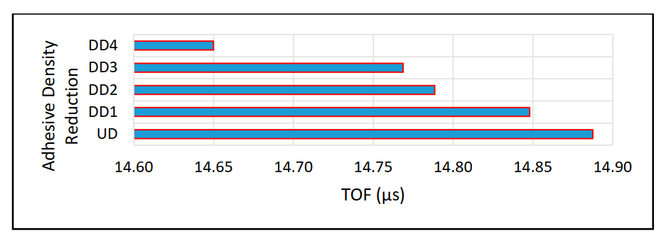 Figure 16. Time of flight of interface wave as a function of adhesive density.
This research summarizes the results of measurable aspects to differentiate good bonds from bad bonds in hybrid bonded joints. Presently there are few known reliable nondestructive methods to determine the integrity of bonded structures. The numerical simulation in this work suggests a reliable and repeatable method of nondestructive inspection using high frequency interface guided waves. The interface wave time-of-flight over a given distance is measured as a function of cohesive and adhesive defect sizes and locations at or near the bondline of structural joints. Results of the simulations indicate that interface waves propagate faster in perfectly bonded hybrid structures as well as parallel to the fiber direction of composites in metal-composite hybrid joints. The time of flight for interface waves increases with increase in length of disbond cracks at the bondline and ply matrix cracks and delamination near the bondline of hybrid joints. If the crack offset distance from the bondline is more than a half wavelength of the propagating wave, then the interface wave is not useful for interfacial damage detection. This technique of using interface waves can also be used to model disruption of interface waves caused by other failure modes like fiber cracking in composites, wrinkles, waviness and kinks in multilayered structures. The pervasive effect of interface wave disruption can be quantified and used in the development of experimental test setups for actuator—sensor placement of a novel pitch—catch ultrasonic structural health monitoring system, designed for smart laminated and hybrid structures. The use of ultrasonic interface guided waves can be extended to damage detection of several other damages and defects such as in curved structures and of rough surfaces.
This research is reprinted in part with permission from Villanova University office of graduate study and partially from the unpublished PhD dissertation of MJ. This study has been reviewed by SS, the student academic advisor chair and faculty of mechanical engineering department.
The dataset of the study is available from the authors upon reasonable request.
The authors declare that they have no conflicts of interest.
1.
2.
3.
4.
5.
6.
7.
8.
9.
10.
11.
12.
13.
14.
15.
16.
17.
18.
19.
20.
21.
22.
23.
24.
25.
26.
Jahanbin SM, Santhanam S. Interface Waves for Detecting Defects in Bonded Hybrid Joints. J Acoust. 2020;2:e200002. https://doi.org/10.20900/joa20200002

Copyright © 2020 Hapres Co., Ltd. Privacy Policy | Terms and Conditions